
Surface And Foul
_
Specialist surface water drainage:
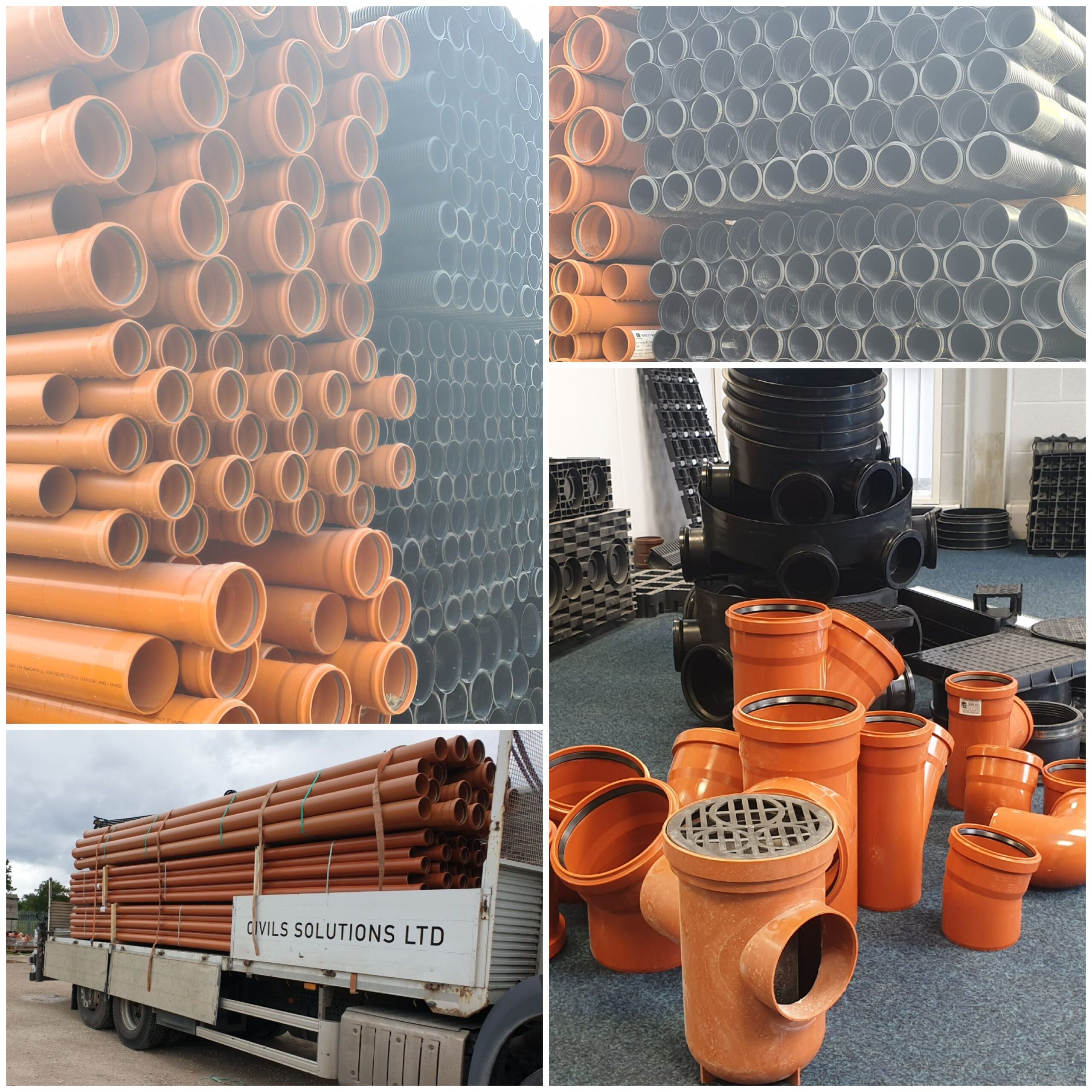
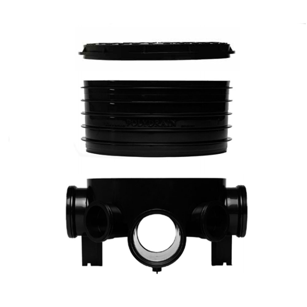
Independent Civils Solutions are specialists in surface water drainage, stocking a full drainage system encompassing all elements including BBA approved pipework, a full range of fittings and inspection chambers.
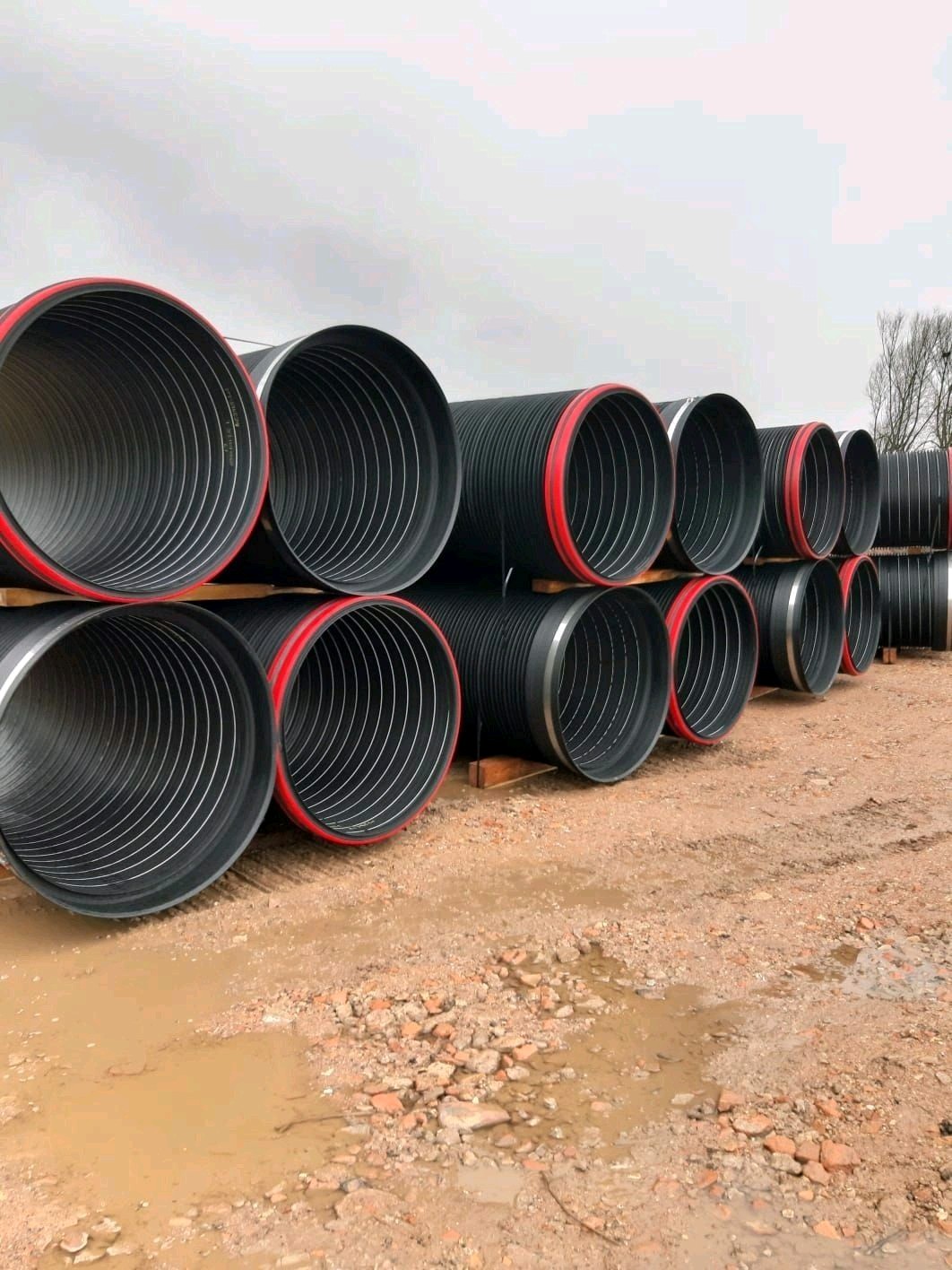
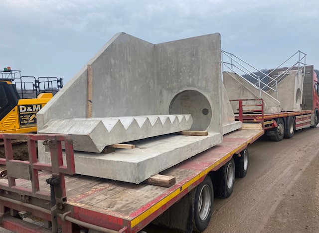
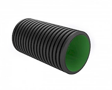
We can also offer fully adoptable large diameter drainage systems, flow controls, penstocks & headwalls.
Speak to one of our knowledgeable members of staff who can tailor a quote to your site requirements
- Full Stock
- Full Support
- Sustainable
- Innovative
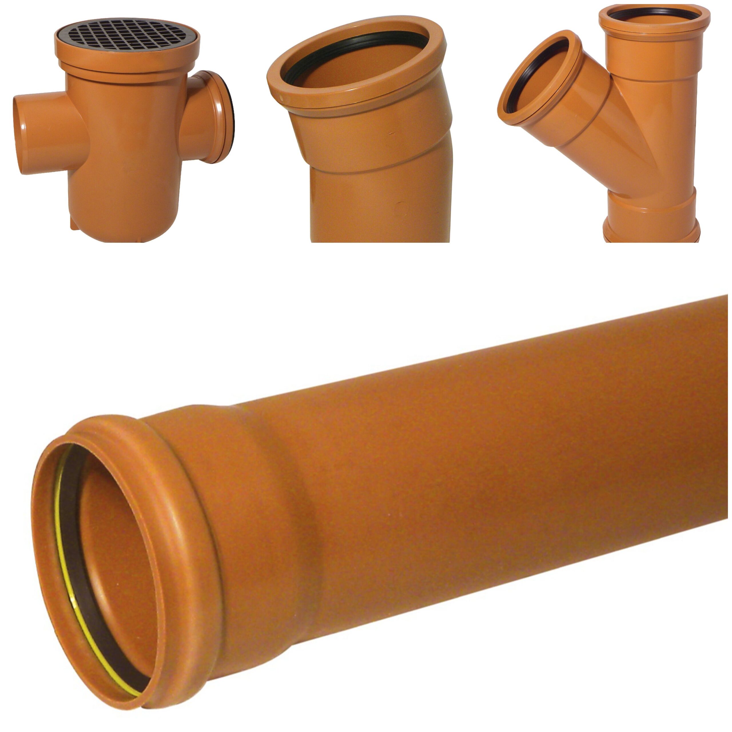
- Socketed Underground Pipe combines reliable connections with the latest in blown end technology.
- A plastic circular insert holds the rubber seal in place during transit and also provides an ideal connection for jointing.
- All underground fittings utilise seal and snap technology, avoiding sharp edges and allowing for an easy fit connection. The seal is double ribbed, whilst the sockets incorporate a recess that provides space for the rubber seal to locate as the pipe is inserted.
- Effective means of waste water drainage and foul discharge from above ground drainage
- Strong and durable, products are also lightweight, aesthetic and easy to install
- Suitable for extreme environments including temperature and waste discharge
- Push-Fit joint achieved using a ‘cap and seal’ system
- A range of fittings available, suiting most installations and can be integrated with Kalsi above and below ground drainage products
- Available in Terracotta Brown
- All ranges are compliant with British Standards
Step by Step Installation Guide - UNDERGROUND DRAINAGE
_
Step 1
_
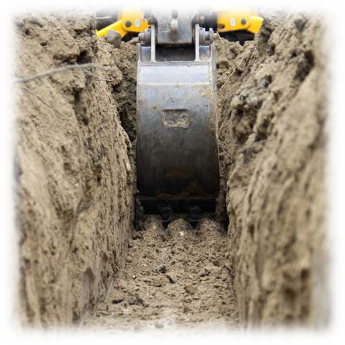
- According to British Standards and Building Regulations, dig your trench.
- We recommend to reference to the current regulations document, BS EN: 752: 1997 and BS EN: 1610: 1998.
- Where drainage appears internally, BS EN 12056 should also be consulted.
Step 2
_
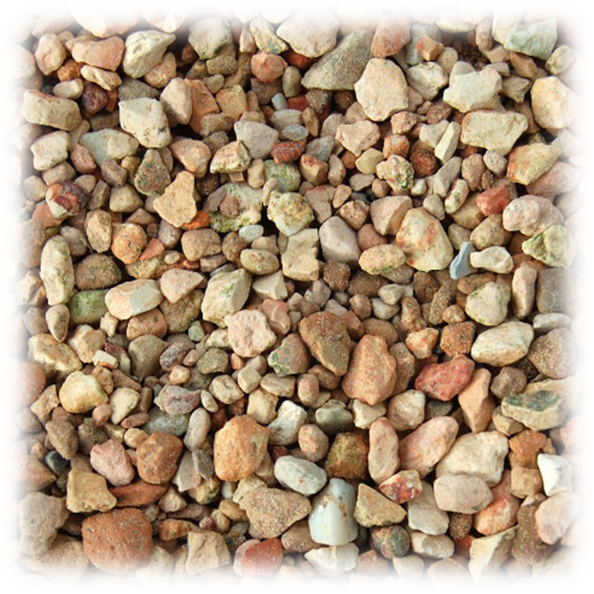
- Drop pea shingles into the trench to create the pipe bed, making sure the pipe is well supported.
Step 3
_
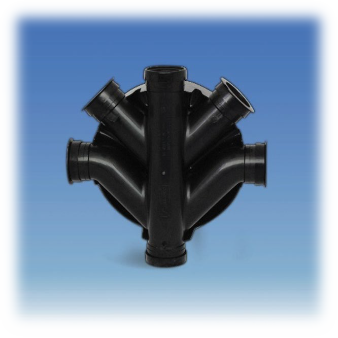
- Decided where the main fittings will be placed. Make sure the inspection chamber is positioned in a way, where the water flow is maintained through the primary channel to reduce the possibility of blockages.
Step 4
_
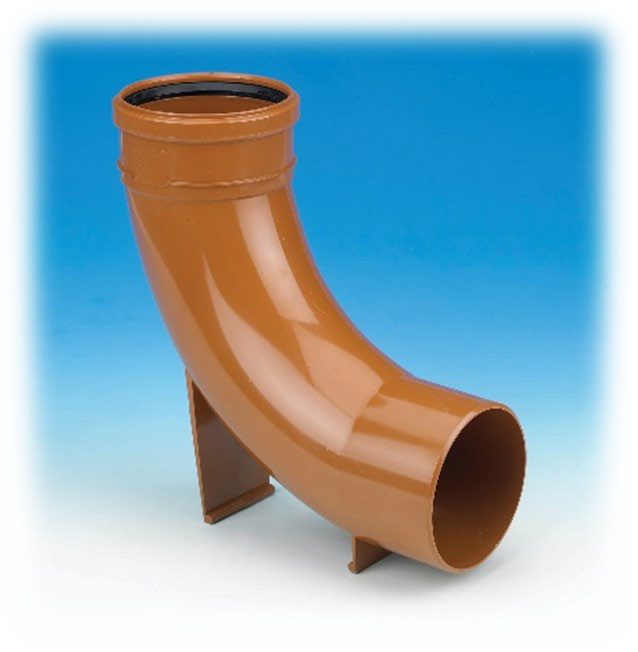
- Place a solid support under the long radius rest bend when connecting to a vertical soil and ventilation pipe.
Step 5
_
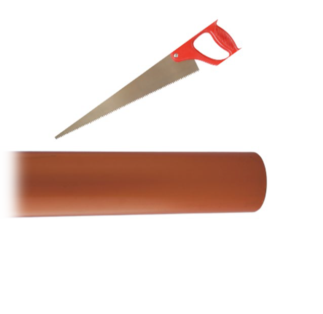
- The length of the pipe connecting the rest bend to the first inspection chamber should be measured and cut.
- When cutting pipes all ends should be chamfered and free of residual material, swarf, grit, and dirt.
Step 6
_
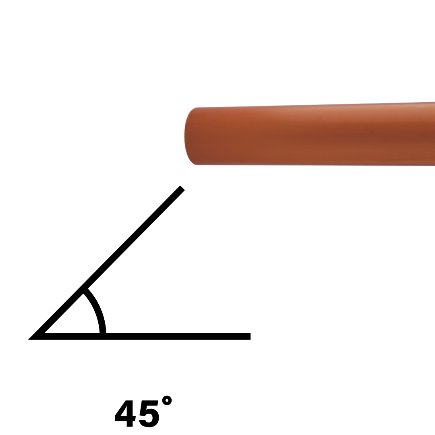
- Make sure all cut lengths of pipe are chamfered as 45° angle to ensure a smooth insertion into the fittings.
Step 7
_
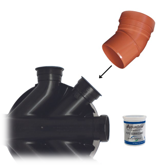
- Use lubricant on the seals to ensure smooth easy insertion without damage to the seals.
- Follow the same method for the remaining fittings.
Step 8
_
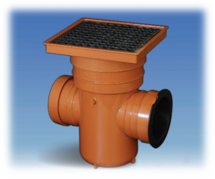
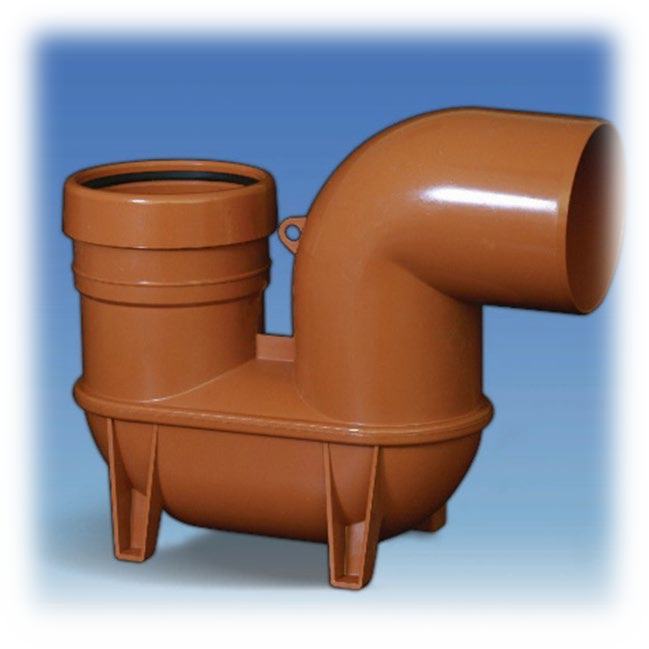
- According to the system, you can add traps and bottle gullies, where applicable.
- In our range we also offer a telescopic bottle gully to allow for different floor levels.
Step 9
_
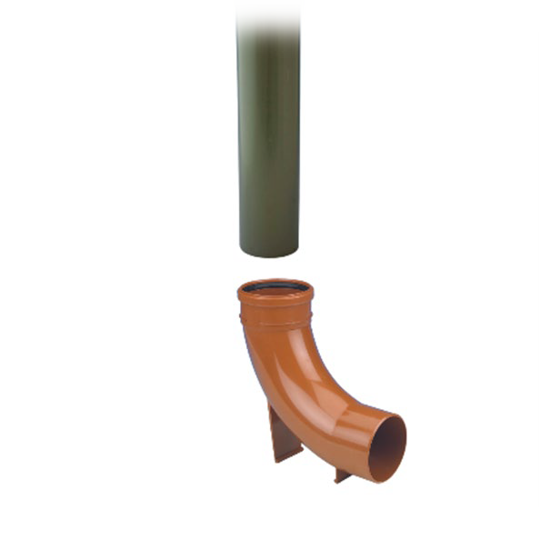
- Use soil pipes to connect them straight into the long radius bend.
- The diameter of our 110mm PVC-U above and below ground drainage systems are the same and a direct connection can be achieved.
Step 10
_
- Rainwater adaptors are used to connect all downpipes, where applicable.
- Connections to other materials such as cast iron, supersleeve and hepsleeve is achieved by using a range of our rigid and flexible adapters and couplings.
Step 11
_
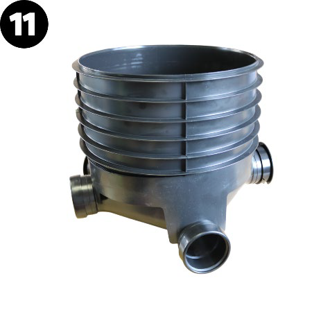
- If you wish to change the direction of your underground system, add another inspection chamber.
- To complete the installation, add raising piece, according to the depth.
Step 12
_
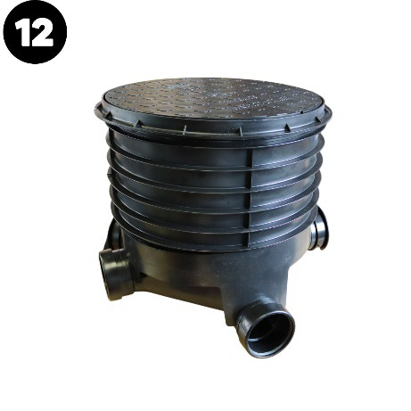
- Large inspection chamber height can be up to a maximum of 1.2m, with the standard 470mm plastic cover and frame.
- Small inspection chamber height can be up to maximum of 600mm, with a standard plastic cover and frame.
Step 13
_
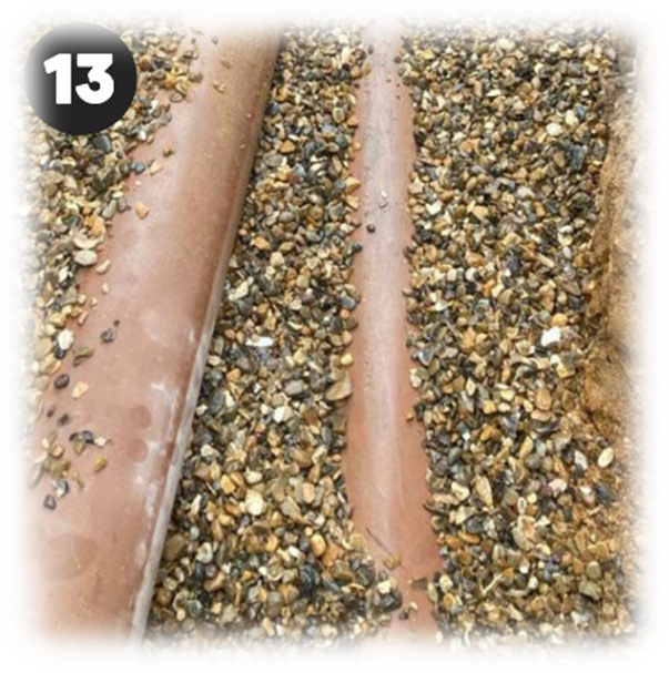
- Once all pipework has been tested then backfill with pea gravel to the crown of the pipework and backfill with the dug-out soil.
Remember
_
- Access is integral to the efficiency of a drainage installation, for testing, inspection or the removal of blockages and debris.
- Rodding points are more commonly used in storm water drainage systems, where the rodding point is located at the head of the drain run connection to a chamber, being no further than 22m away from the chamber.
- The rodding point should be enclosed in a concrete surround to provide support and ensure that it does not become mislaid at ground level.